Until the developments made between 1935 and 1940, Radio Direction Finding (RDF) could only transmit a wide ‘beam’. This could not be used to detect ships as the echo from the vessel would be swamped by those from the surrounding land and sea.
Due to the work carried out by J F Coales and R V Alred of the Royal Navy Signal School, a new system had been developed in Portsmouth. This was known as RDF Type 284 and was used to guide the guns on naval ships. By 1940, these sets were being installed on warships, including HMS Hood which would use RDF to help locate the German battleship Bismarck on 27th May 1941.
As the war progressed, British ports and docks were to become a key target and steps were taken to protect them. Gun batteries were installed at Beacon Hill and Landguard Forts. A boom was installed across the river estuary between the two and supported an anti-submarine net.
The main deterrent was a naval minefield located across the mouth of the river. This was to be monitored from a new tower being built outside Beacon Hill Fort, the tower you are in today. Once complete, the hexagonal, brick tower was fitted with a modified RDF Type 284 set, designated RDF Type 287.
This floor of the tower was called the Operations Room. It would have been in here that the work was carried out to locate vessels approaching the minefield.
Type 285 ‘Office’
The heart of the RDF system is known as the ‘Office’. It consists of various components and cabinets, depending on the Type. Most of these components were interchangeable and faulty units could be removed and replaced fairly easily.
This particular example is a representation of a Type 285 ‘Office’ which would have been similar to the Type 287. Unfortunately, there does not appear to be any illustrations actually showing the equipment used in Type 287, such as here at Harwich RDF Tower.
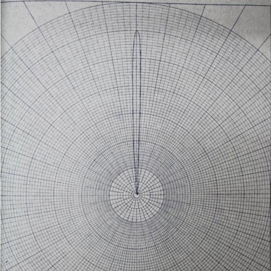
The larger unit on the left would house the receiver side of the system including the L12 Ranging panel in the centre of the console. The ranging panel was a Cathode Ray Tube (CRT) which would show the range of the vessel detected by the RDF array.
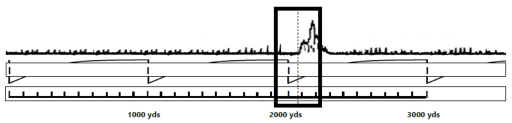
Below is an example of a trace that would be shown on the CRT screen. The upper trace is the RDF signal, showing a possible target at 2100 yards. The lower trace is the calibration trace, each sharp trough indicates a 1000 yard range.
The width of the trace on the screen is set to a maximum range of 3500 yards, an adequate range to cover the entire minefield.
Below the L12 Ranging Panel are a row of adjustment knobs (from left to right):
- Gain – Used to magnify the receiver signal (upper trace)
- Brilliance – Makes the signal trace brighter, although too bright can burn the face of the CRT screen and cause eye strain
- Focus – Varies the definition of the trace
- Scale correction – Adjust both traces to match the paper scale
- Vertical shift, horizontal shift and scale shift
Radio Tuning Unit
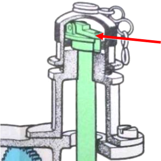
The smaller unit to the right was called the Radio Tuning Unit (RTU). This included dials, showing range and bearing, along with adjustment wheels and protected adjusters. There are five covers with short lengths of chain seen on the front of the unit. These are protected adjusters, enclosed by a removable cover.
If an adjustment was needed, the cover would be unscrewed, revealing a small handle (arrowed in the diagram). The handle would be unfolded, the adjustment made and the cover replaced. The short length of chain was simply needed to prevent the cover being removed and lost.
In the centre of the unit is an adjustment wheel. This wheel was connected to the L12 ranging panel by a flexible coupling.
When turned, the target locator would move across the CRT screen.
The units were quite large by today’s standards, due to the size of components being used at that time. Instead of computer processors and transistors, the equipment relied on glass valves and mechanical gearing.
Connections that can be made today using wires, would have been made with cogs and drive shafts. It was the advance in glass valves that made the Type 285 system possible. Until the 1930’s, valves were not able to generate the frequencies needed to operate such a system.
This set would have only been used for a short length of time. It was installed in April 1941 but had been decommissioned by December 1943. It would have only been used at night or times of poor visibility, when incoming vessels could not be seen from the EXDO towers.
The following block diagram shows the major components of the Type 287 set, the type used in this tower.
Back Continue