The top floor of the tower is dominated by a rare survivor, a largely original example of a Type 287 array. When the tower was cleared, a jumble of metal was discovered on the ground floor, below the equipment hatch. On investigation, it was found to be the remains of the array, a key component in the RDF system.
The array is made of two parts, the transmitter at the top and receiver at the bottom. Each is made of a steel frame supporting a sheet metal ‘pig trough’, concave reflector. Both the transmitter and receiver would have held 24 dipole elements along the front, these would have sent or received the signal, generated by the Type 287 ‘Office’ on the floor below.
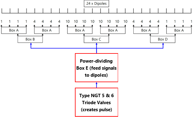
The signal would be sent from the ‘Office’ to power-dividing box E. It would then be passed on to boxes B, C and D before arriving at boxes A. The key part of the Type 287 system was its narrow ‘beam’, which made it possible to detect vessels at sea level.
The narrow ‘beam’ of the Type 284, the predecessor of the Type 287, was achieved by varying the power to different sets of dipoles. Maximum power was fed to the centre sets, four-tenths to the next sets and finally one-tenth to the two outer sets.
To make the ‘beam’ narrower, the power ratio at the dipoles may have been 10 – 3 – 0.75 for the Type 287 RDF.
Aerial
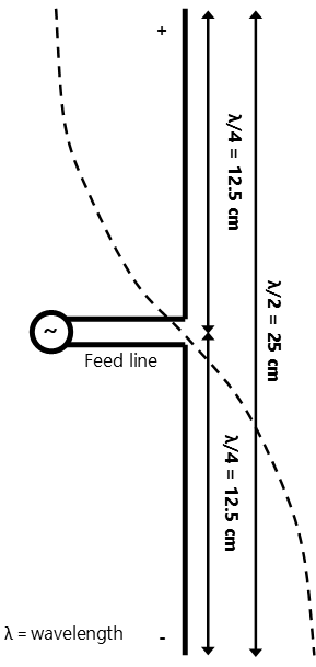
Vertical half-wave dipoles
Along the front of both the transmitter and receiver is a row of dipole elements. Each dipole is 25cm from top to bottom, this is half the wavelength of 50cm.
One half would be positively charged, the other half negative. The dipoles were installed side by side, half a wavelength (25cm) apart as can be seen on the array.
Pig-trough reflector
As with an electric fire or torch, these polished metal reflectors were installed to stop the signal being wasted by travelling in the wrong direction.
The surface of the reflector is a parabola – a curve decreasing as it goes away from the centre (apex) – which focuses the ‘beam’. The current reflector here at Harwich is a replica, although the framework is genuine.
Broadside, Multi-Aerial Array
This rare survivor was a state of the art piece of equipment during WWII. However, the process of directing it across the minefield was much simpler.
The structure is mounted on top of a surplus turntable from a 3.7 inch antiaircraft gun. A connecting shaft runs down through the floor to the level below. In the centre of the operations room, two members of the crew would manually turn the array, allowing it to detect incoming vessels.
Technical details
- Radar Type 287
- Radio Direction Finding (RDF)
- Derivation
- Type 284 ship gunnery control (Royal Navy Signal School, Portsmouth)
- Installers and Operators
- Admiralty Local Defence Division
- Installation Date
- April 1941
- Frequency/Wavelength
- 600Mc/s (MHz) – 50cm
- Peak Power Consumption
- 15 kilowatts
- Power Source
- Petter 3000 RPM diesel-electric generator
- Carrier Wave ‘Driver’
- Resonant cylinder, 1x NG5 and 1x NG6 Thyratron Triode Valves
- Pulse Modulator
- 2x NT93 Triode Valves (paired)
- Pulse Recurrence Frequency
- 500 per second
- Pulse Width
- 2 milliseconds
- Aerials
- Double (transmitter and receiver) broadside, each of 24x vertical halfwavelength dipoles with ‘pig trough’ parabolic reflector (hand rotated)
- Horizontal Polar Lobe (signal width)
- 5 degrees
- Radio Frequency Receiver Valves
- V91 Pentodes
- Time Base and Cathode Ray Trace
- Probably set at 2.5 miles and 25 milliseconds
- Cathode Ray Tube
- Type A
- Reporting System (RDF Tower to EXDO Towers)
- Magslip and Telephone
- Full Crew
- 8x Royal Navy ratings (may have been guarded by 12x Royal Marine Guards)
- Decommissioned
- c. December 1943
Back Continue