Until the developments made between 1935 and 1940, Radio Direction Finding (RDF) could only transmit a wide ‘beam’. This could not be used to detect ships as the echo from the vessel would be swamped by those from the surrounding land and sea.
Due to the work carried out by J F Coales and R V Alred of the Royal Navy Signal School, a new system had been developed in Portsmouth. This was known as RDF Type 284 and was used to guide the guns on naval ships. By 1940, these sets were being installed on warships, including HMS Hood which would use RDF to help locate the German battleship Bismarck on 27th May 1941.
As the war progressed, British ports and docks were to become a key target and steps were taken to protect them. Gun batteries were installed at Beacon Hill and Landguard Forts. A boom was installed across the river estuary between the two and supported an anti-submarine net.
The main deterrent was a naval minefield located across the mouth of the river, to be monitored from this new RDF tower. Once complete, the hexagonal, brick tower was fitted with a modified RDF Type 284 set, designated RDF Type 287.
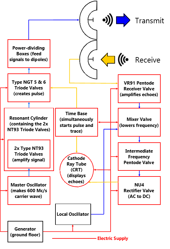
Transmission
Generator
Situated on the ground floor a generator, similar to the one seen today, supplied electricity to all the components of this system. It also supplied power to the magslips, lights and heaters in the tower.
Master Oscillator
When the 50 hertz (cycles per second) is applied to these crystals they vibrate at 600 megacycles/second (Mc/s). This is the carrier wave frequency required.
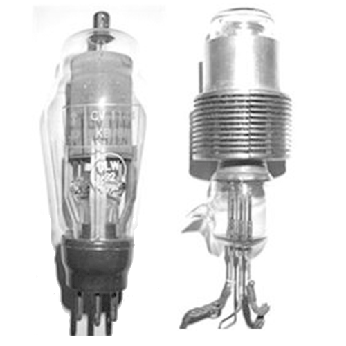
NT93 Triode Valves
The very faint signal from the master oscillator is magnified by two NT93 valves. These valves run very hot due to the ultra high frequencies they generate.
For that reason, they are embedded in copper rings which branch out into numerous thin ‘fins’ outside the glass. The heat from within is dissipated into the air, thereby preventing the valves overheating.
Resonant Cylinder
The vibrating copper cylinder, about the size of small tea urn, amplifies the electrical signal. Whilst it was the correct frequency, it was far too weak. Later in the war it was replaced by a new device called a magnetron.
NGT 5 and 6 Triode Valves
These were gas-filled ‘Thyratron’ type valves. The mercury vapour inside blocks the electrons for a moment then suddenly pulls them through and amplifies them. Every 1/500 of a second they modulate the 600 Mc/s carrier wave into the sharp pulse needed to operate the system.
The modulated signal was then sent to the power dividing boxes before being sent to the dipole elements fitted in the array on the top floor of the tower.
Reception
The signal transmitted from the array on the next floor headed out across the minefield and would be reflected from any potential target. The return signal would be picked up by the lower part of the array and passed to the receiver in the operations room. The complicated process involved in displaying the information is outlined below.
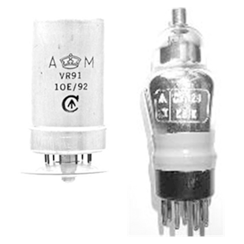
Receiver Pentodes
These were probably the Naval Receiving (NR) 71 and Valve Receiving (VR) 91 types. They would take the weak electron flow from the receiver aerial through its heated cathode and focus it towards the anode by means of one grid.
It would be amplified through a second grid and then passed through a third grid to prevent a back-scattering of electrons.
Local (receiver) Oscillator and Mixer
This causes a crystal to create a Ultra High Frequency (UHF) wave, slightly lower frequency than that of the RDF. The RDF and local oscillator wave are overlaid in the mixer valve, this results in a much lower frequency, equal to the difference of the two. This new ‘intermediate’ frequency is sent to the Cathode Ray Tube (CRT).
Rectifier
This is a valve which turns Alternating Current (AC) into Direct Current (DC). This is necessary as AC would disrupt the ‘blips’ on the screen. This was probably a NU4 valve.
Cathode Ray Tube (CRT)
This is the part of the equipment that changes the electrical signals into a visible trace across the screen. This allowed the operator to see the range and, to some extent, the size of the target.
The structure and operation of the aerial array will be discussed in detail on the upper floor of the tower.
Back Continue